
Pseudo-Neon Sign
The first video at right shows the bare LEDs, without a diffuser or face. In the second, a diffuser is laid on top so the bare LEDs aren't seen, but without a face everything is fuzzy. The last video shows the face layer in place, and it becomes a sign.
The software is just a simple sequencing, more work is needed there. Also need a much bigger power supply, you can see a taper to orange when all white was attempted.
Most of what's below needs updating:
I'm planning to make a lighted sign for my sister and brother-in-law's jewelry studio. It will be about 24" high and 18" wide, hanging from the wall above their door. I call it pseudo-neon, and if I were strict each element would follow the glass bending constraints of a true neon sign. Since this project will be the first thing their customers see, it must stay consistent with the established graphical design. That includes the logo inside the diamond below, and the artist names. You can see these elements in their web site: http://www.trkd.com/
I want to avoid any pixelated or digital feel in the final result, so I'm planning to use shadow boxes behind the sign to get even/analog lighting. That severely restricts the level of animation, but a neon sign has a similar problem. I'll light each shadow box with multiple discretely controlled LEDs, keeping them all the same color. I can play with sequencing the individual LEDs to get a fuzzy animation, but that's not a goal. If it looks nice, again, the rules aren't strict.
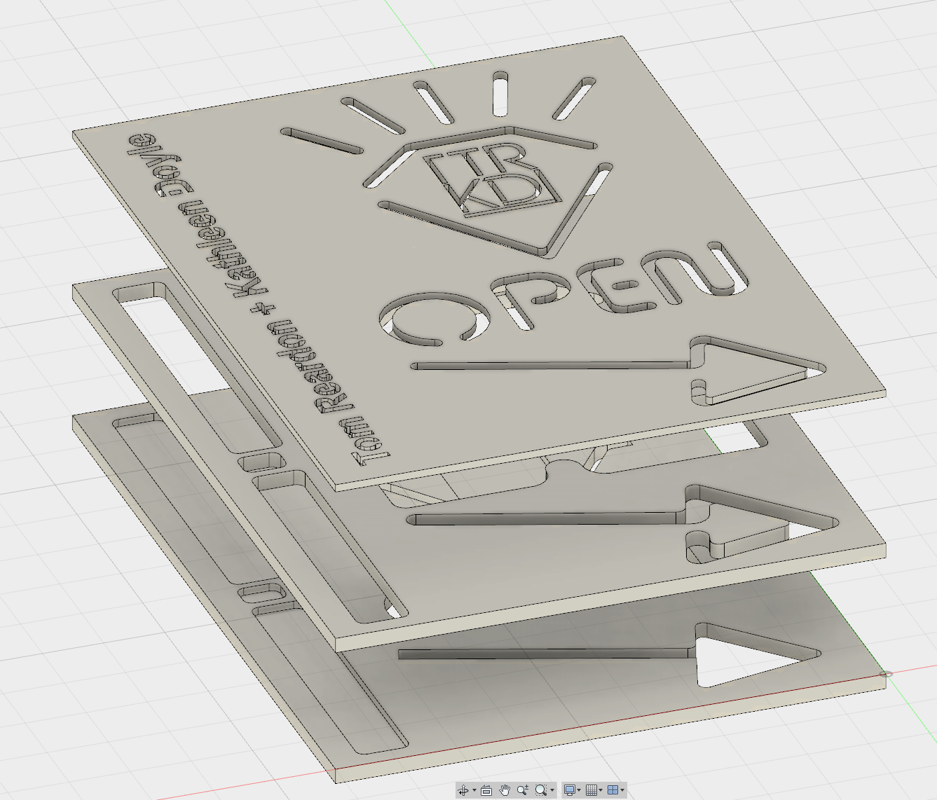
Here's a recent design. The top layer is the face, where the design elements are cut. A diffusion layer (not shown) sits below the face to scatter the light. The next layer shown is the shadow box, which separates the LEDs from the diffusion surface, so adjacent LEDs blend without pixelation. The bottom layer is the LED mount, which is still in progress.
Old Approach
I'll focus on the three pseudo-neon elements first: the diamond (without the logo inside), the "OPEN" text, and the arrow. Each will be backlit from separate shadow boxes, so they can be different colors. The arrow will be animated in the classic left to right sequence, and twinkles on top of the diamond need to twinkle. For now I plan to create smaller shadow boxes for each animation sub element.
Bare LED layer
Diffused sign without face
Complete sign, all layers present

Computer Aided Design (CAD):
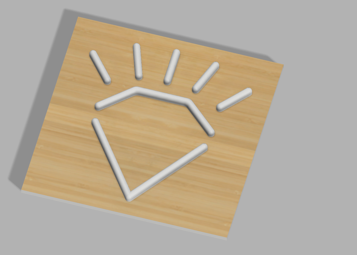
I've got the plain diamond modeled, shown in the CAD software on the left. This plexiglass layer goes above the shadowbox. A masking layer will go on top, a rendering of the stackup is shown on the right with wood masking.
There are a lot of ways to do this. I've already used a laser cutter to make a prototype masking layer in 1/8" plywood, that was pretty simple. I've also got access to a vinyl cutter so could also do the masking layer in graphics tape. The layers could be swapped, if the plexiglass finish for the flat sections is good after machining. Color/finish is TBD, but they are leaning towards steel with a rusty patina. CNC plasma cutter is on the way.
Plexiglass Machining???
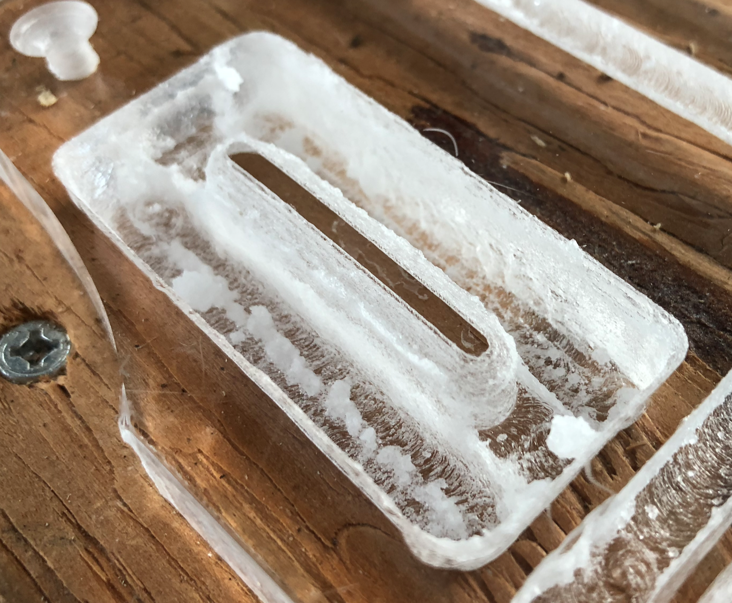
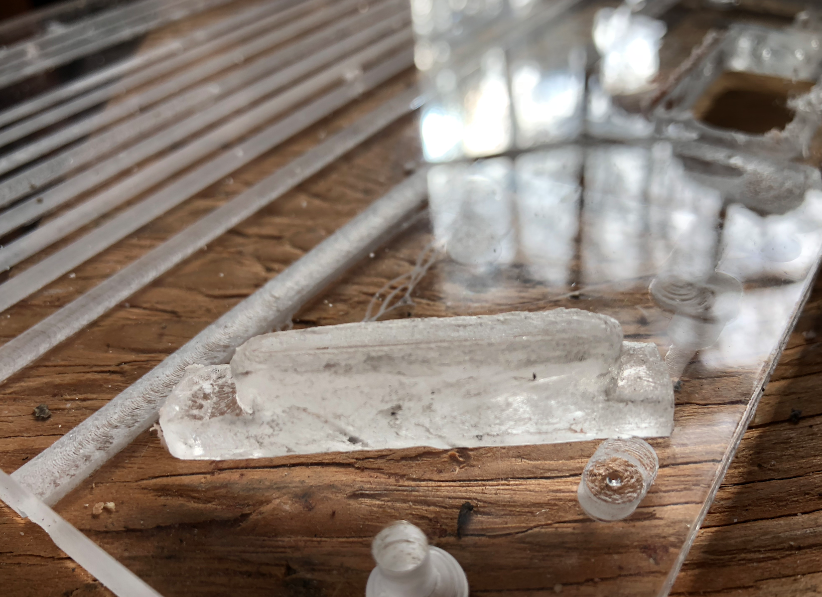
My first approach was to machine the entire plexiglass layer on our CNC router. Not such a good idea, looking back. Plexiglass/acrylic is brittle, and melts easily. I hope to create a page showing the fails, but for now here's a "Twinkle" in plexiglass. It needs some finish work, and that's the main reason I don't like this approach. This one took 20 minutes on the router. I could do better but it would probably take an hour or two, for a single Twinkle.
Here is the original concept, machining the entire surface:

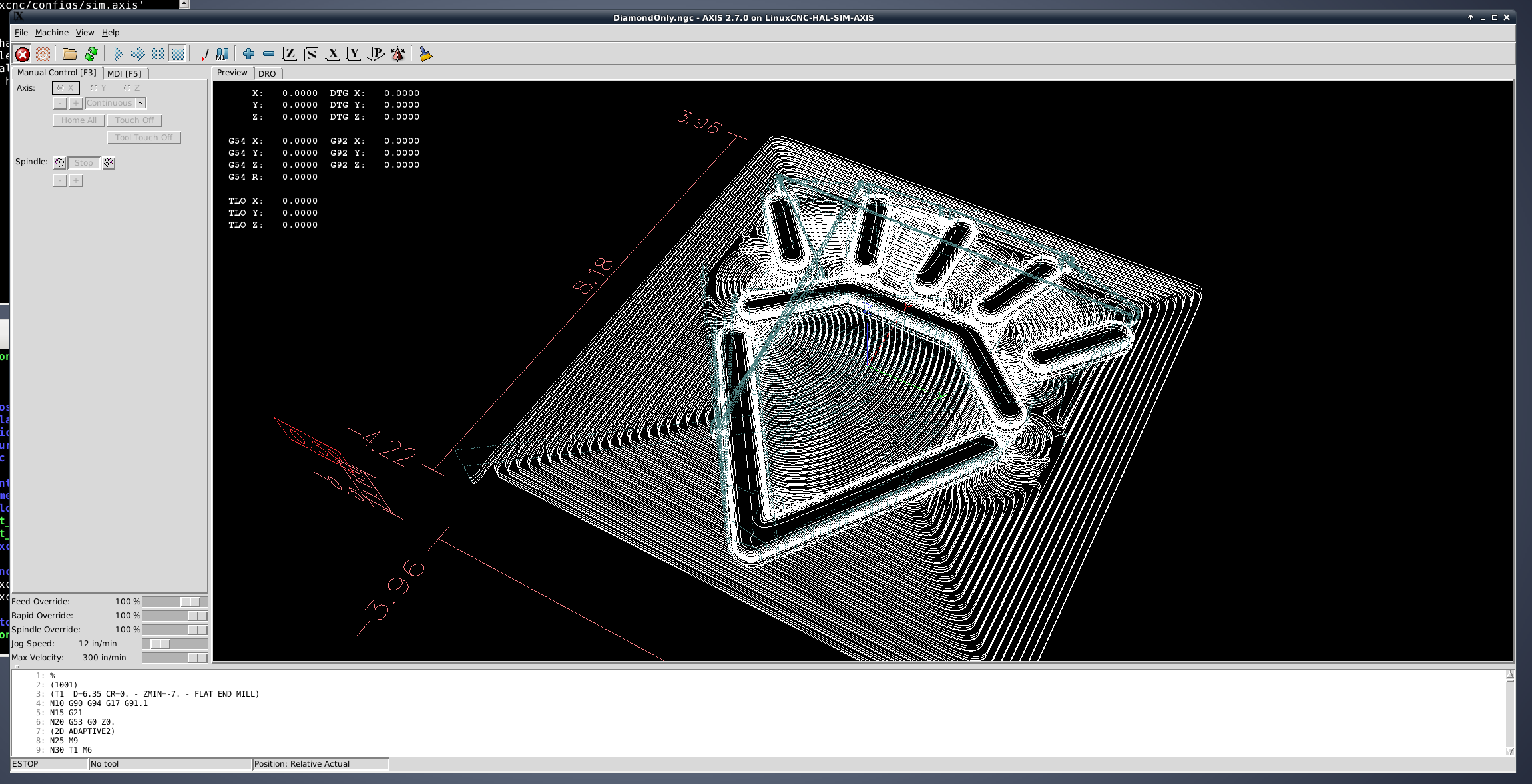
Computer Aided Manufacturing (CAM)
Toolpaths are shown in the CAM software the left, and then again in the machine control software.